
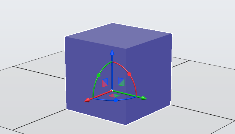
Gizmo
A tool for manipulating object in a 3D environment.
ABB ROBOTICS
Research
UX
UI
User Testing
Goal:
Redesign the 3D manipulation experience in robot simulation software to balance precision, speed, and learnability for both novice and expert users working in complex spatial environments.
Outcome:
The new 3D gizmo tool was shipped across both desktop and web platforms, aligning interaction patterns and delivering a consistent experience for robot programmers, resulting in improved efficiency and user satisfaction.
My Role
Led end-to-end UX for redesigning the 3D manipulation experience, from research and concept definition through usability testing, final design, and engineering implementation support.
Tool & Process
- Figma Design: UI design and interactive prototyping.
- Design Sprint: Ideation, problem framing, and concept development.
- SAFe Methodology: Agile project execution through prioritized, task-based iterative development.
Overview
Project Aim
Understand how robot programmers interact with 3D objects in a graphical environment to support both rapid layout creation and precise positioning of targets and paths, while ensuring they feel supported, confident, and in control.
Key Design Challenges
- Enabling robot programmers to manipulate 3D objects with confidence and a strong sense of control.
- Improving precision and efficiency without increasing interaction complexity.
- Supporting expert workflows while keeping the learning curve low for new users.
Process


Sections
Click to navigate →
Research
Understanding use cases and current situation
The first step in the process was to evaluate the current tools and understand users’ existing workflows and pain points.
This included:
- Hands-on testing: interacting with 3D objects in the graphic environment using the current tools to experience usability first-hand.
- User interviews: speaking with robot programmers to gather their perspectives on the existing interaction model.
The original tool

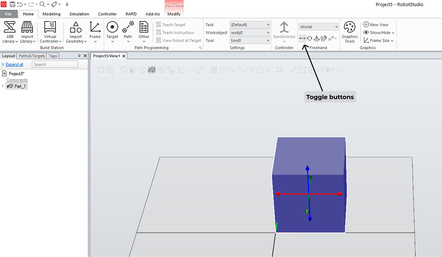
The original 3D manipulation experience presented two tool variations, one for translation and one for rotation. The user could switch between these in the application toolbar using two buttons, when using these two functions in parallel it meant shifting focus and moving the cursor back end forth between the object and the toggle buttons.
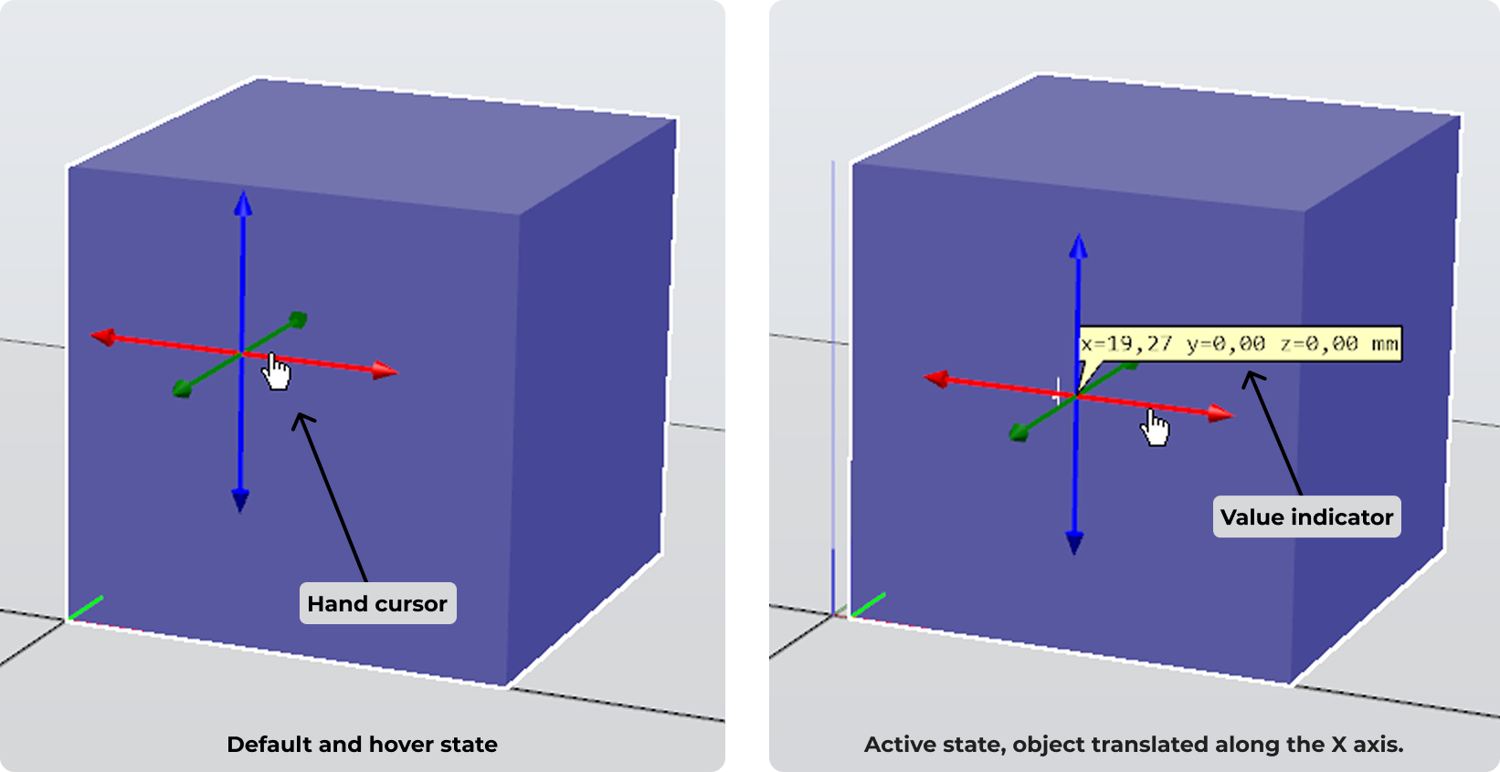
The only affordance showing that the tool can be interacted with is displayed when the cursor changes to a hand on hover.
There is a indicator showing the values of the coordinate positions for X, Y and Z axes but there are no guidance to which coordinate belongs to which tool axis and when all 3 axes values are shown independent off which axis the user is currently interacting with it can lead to confusion and errors.
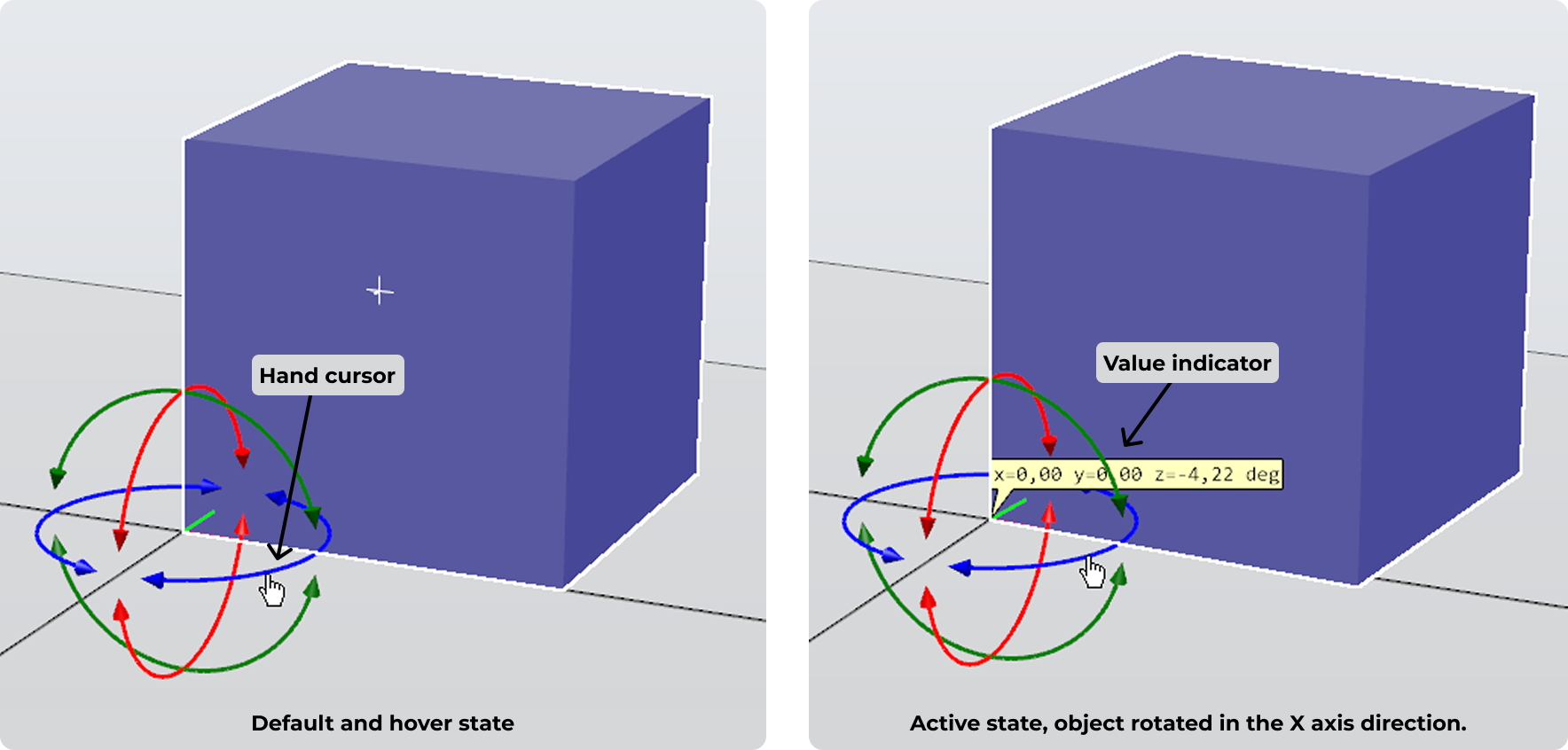
The rotation behavior is quite unexpected as it rotates the object around the world coordinate system zero point and not the objects own center point.
User Perspective

The Robot Programmer
I usually start with a rough layout to understand how the robot should be positioned in relation to the workpiece inside the cell. Getting the reach, angles, and accessibility right early on saves a lot of time later. Once I move into programming, precision becomes critical. The robot has to handle parts with high repeatability, and when it comes to welding, tolerances are tight so even small deviations can affect quality
Positioning objects is the 3D environment is part of by daily work.

When starting a new project I need to find a layout that works for the automation application I am building.

Defining the layout of a robot cell often requires several iterations, it is important that the robot can reach all parts of the work station to preform its task.
The demand for precise positioning is high, it often comes down to millimetres.
The objects you need to position is of course the robot, conveyors and other machines included in the station, but also the points (targets) in the path the robot moves along to perform work.
Key Insights / Pain Points:
- Users felt restricted and inefficient because moving and rotating objects required switching between two separate tools, which is tiresome when performing combined actions multiple times.
- The existing tools provided very little feedback, making it difficult to anticipate which axis an object would move along, leading to errors.
- The rotation tool behaved unexpectedly, rotating objects around the world coordinate system zero by default instead of the object itself, causing confusion and low adoption.
- Users lacked control and precision, forcing them to roughly position objects in the graphical interface and then rely on a control panel to set exact coordinates or distances for each axis.
Impact:
These issues made the 3D manipulation experience slow, error-prone, and frustrating, reducing overall efficiency and confidence in the workflow.
Benchmark
As a second step to inform the design, 3D manipulation tools from robot simulation, CAD, and 3D modeling software were evaluated to identify their strengths, weaknesses, and interaction conventions.
Domains evaluated:
- Robot simulation software: To understand industry-specific workflows and requirements.
- CAD and 3D modeling software: Recognized for precision and expertlevel 3D manipulation.
- Architectural tools and games: Known for intuitive, efficient layout and assembly interactions.
Key Outcomes / Insights:
- Created a benchmark comparison of 3D manipulation tools across robot simulation, CAD, and 3D modeling software, highlighting strengths, weaknesses, notable features, and design opportunities.
- Identified common conventions such as frequently used functions, interaction patterns, and keyboard shortcuts that users expect across 3D environments.
- Extracted transferable patterns and principles that could be adapted to improve efficiency, precision, and learnability for robot programmers.
- Evaluated visual and interaction affordances of manipulation tools, recognizing that shape, color, size, and placement play a critical role in communicating how a tool should be used and interacted with.
Example of findings from benchmark comparison:
- Tool structure: Single vs. combined manipulation toolsSome software separates translation, rotation, and scaling into three distinct tools, each activated by a dedicated button. This approach reduces complexity per tool but requires more clicks to changes between the tools. Others softwares combine translation, rotation, and scaling into a single tool activated with one button, reducing amount of clicks but potentially increasing visual complexity and cognitive load.
Individual transform tools for translate, rotate, and scale.
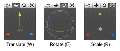
Image source: Unity
All-in-one translation, rotation and scaling tool.
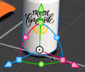
Image source: Adobe Dimensions
- Visual appearance: Impact on perceptionLarge differences in the portrayed feeling of the gizmo tool depending on line thickness and color nuances and saturation making some fell more childish and playful while others came across like more serious and professional. This is an aspect to consider to make the 3D manipulation tool fit the context of use, for example in a game engine or in a professional 3D modeling tool.
Saturated colors and thick lines signals more playfulness.
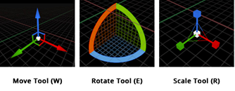
Image source: Unreal Engine.
Soft colors slim lines signals more seriousness.
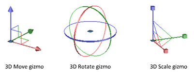
Image source: Autodesk Inventor
- New functions: Plane-based translation and scaling.Many tools presented an option to translate an object along a plane, meaning along a two-dimensional surface involving two axes at the same time, as well as functionality to scale an object. These were non-existing functions in our 3D object manipulation experience, raising the question of whether including them in the redesign would bring value.
Plane-based translation


Image source: Unreal Engine, Adobe Dimension and Autodesk inventor.
Scale
Image source: Unreal Engine, Adobe Dimension and Autodesk inventor.
- Affordances and interaction statesMost evaluated tools provided strong visual affordances through distinct interaction states, including default, hover, and active. These state changes helped communicate interactivity, clarified which control was currently engaged, and reinforced user confidence during manipulation.
Clear differences between default, hover and active state.
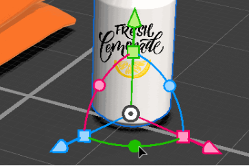
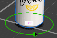
Image source: Adobe Dimensions
Clear differences between default, hover and active state.
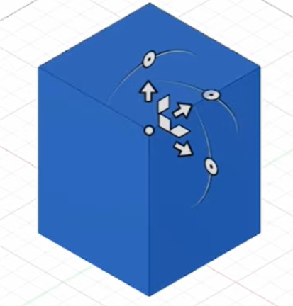
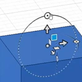
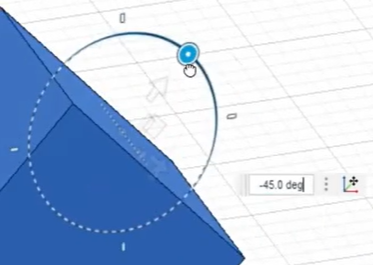
Image source: Autodesk Fusion 360
- Supporting functions and guidance It was common for 3D manipulation tools to present supporting functions, such as rulers and numeric values, in the active state to help users understand how much they had translated the object and to support precise movements.
Supporting rulers with increments.
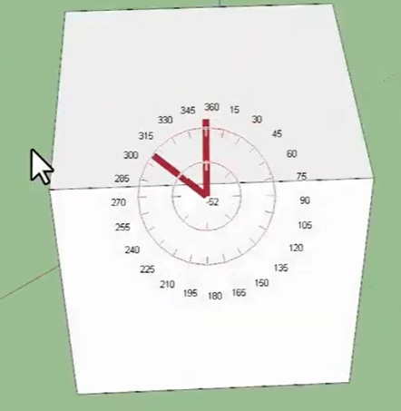
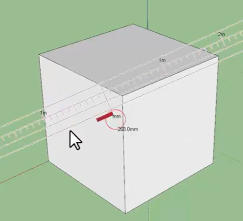
Image source: Sketchup
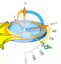
Image source: SolidWorks
Numeric value displayed and editable.
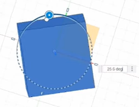
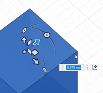
Image source: Autodesk Fusion 360
- Cross-Interaction Inspiration: Adaptive SpeedOpportunities were identified by examining interactions beyond direct object manipulation. For example, in some tools, viewport zoom speed adapts based on distance to the target: zooming is faster when far away and slows as the camera approaches the object, allowing for fine-tuned control. This adaptive speed behavior suggested a potential interaction pattern that could be translated to object manipulation, where movement speed dynamically adjusts based on context to balance efficiency and precision.
Impact:
The benchmark identified familiar conventions and transferable patterns, providing evidence-based guidance to design a 3D manipulation system that balances precision, efficiency, and learnability.
Literature Review
As part of the research phase, existing literature and prior work on 3D interaction and object manipulation were reviewed to identify best practices and domain conventions relevant to designing the new 3D manipulation tool. The review focused on how users interact with 3D objects, common interface conventions, and strategies to support both novice and expert users.
Key Findings:
- Axis conventions: Standard color coding for translation along axes (red = X, green = Y, blue = Z), helps users quickly understand movement direction and reduces cognitive load. This convention is widely adopted across 3D software, providing users with a familiar interaction model.
- Movement constraints: Allowing objects to also be move along a plane (e.g., a “floor” or “wall”) can make spatial manipulation more intuitive and efficient, especially for tasks aligned with real-world surfaces.
- Mental models: Users generally expect objects to move and rotate relative to their center of gravity, but providing the option to adjust the manipulation pivot (e.g., to an edge or corner) supports precise placement and alternative workflows. Aligning interaction tools with users’ mental models increases predictability and reduces errors.
Impact:
These findings informed the visual design, interaction constraints, and user expectations for the new 3D manipulation tool. By following established conventions, the interface feels familiar to users with prior experience in 3D software, while also incorporating enhancements to improve precision, learnability, and flexibility for complex tasks.
Design
Design Sprint
The design phase started with a focused 3-day design sprint to explore alternatives and clarify a viable direction for 3D object manipulation in a spatial environment where the existing tool lacked clear affordances and created friction during precision tasks.
Rather than aiming for a single polished solution, the sprint was exploratory, focusing on uncovering opportunities, testing assumptions, and understanding how different interaction models might support both novice and expert workflows. The design sprint format was chosen to quickly define a direction and evaluate ideas in the context of a complex interaction problem.
Process and Methods:
Problem Framing
Expert interviews
User journey mapping
Rose, Thorn, Bud
How might we
Understand & Define
Success matrix and signals
Personality sliders
Golden path
Sketch
Association exercises
Negative brainstorming
Crazy 8’s
Morphological chart
Decide
Art museum
Heat map
Speed critique
Straw pull & Supervote
Create concept
Prototype
Storyboard
Rapid prototyping
Sprint planned with inspiration from Google Design Sprint kit.
Design Focus Areas:
Interaction Behavior
The existing manipulation tool provided limited guidance, which created friction for users working with precision in complex 3D scenes. Exploration during the sprint focused on identifying interaction behaviors that could better support user intent while avoiding unnecessary complexity.
Areas of focus included:
- Improving affordance clarity during manipulation.
- Supporting both coarse and fine-grained adjustments.
- Reducing accidental or unintended movements.
- Providing clearer feedback during active interactions.
Key Exploration Areas:
The sprint explored a range of interaction and visual strategies, including:
- Pairing direct manipulation with real-time numeric input to support precision without breaking flow.
- Adaptive movement speed based on cursor behavior and interaction intent.
- Visual rulers and interval markers to improve perception of distance and scale.
- Variations in gizmo form, color saturation, and visual weight to assess perceived precision and trust.
- Unified manipulation tool combining translation, rotation, and related functions.
- Interaction feedback including hover states and reduced visual noise during active manipulation.
Key Methods:
Rose, Thorn, Bud: Identified positive, negative and opportunity areas in the original tool, aligning the team on what to retain, improve or reimagine.
Rose
- Uses conventional cartesian coordinate colors for X, Y, Z axes.
- Large tool size reduces risk of accidentally grabbing the wrong function.

Thorn
- Need to use button to switch translation type (move, rotate).
- All parts of the tool still visible in active state.
- Not clear how much an object is being translated to its new position.

Bud
- Having one tool with all functionality makes operation more effective.
- Increase affordance on hover.
- Hide all parts of the tool in active state exept the active function.
- Allow user to scale objects.
- Introduce movement along a plane for easy translating along “real life” surfaces like a table or along the floor.

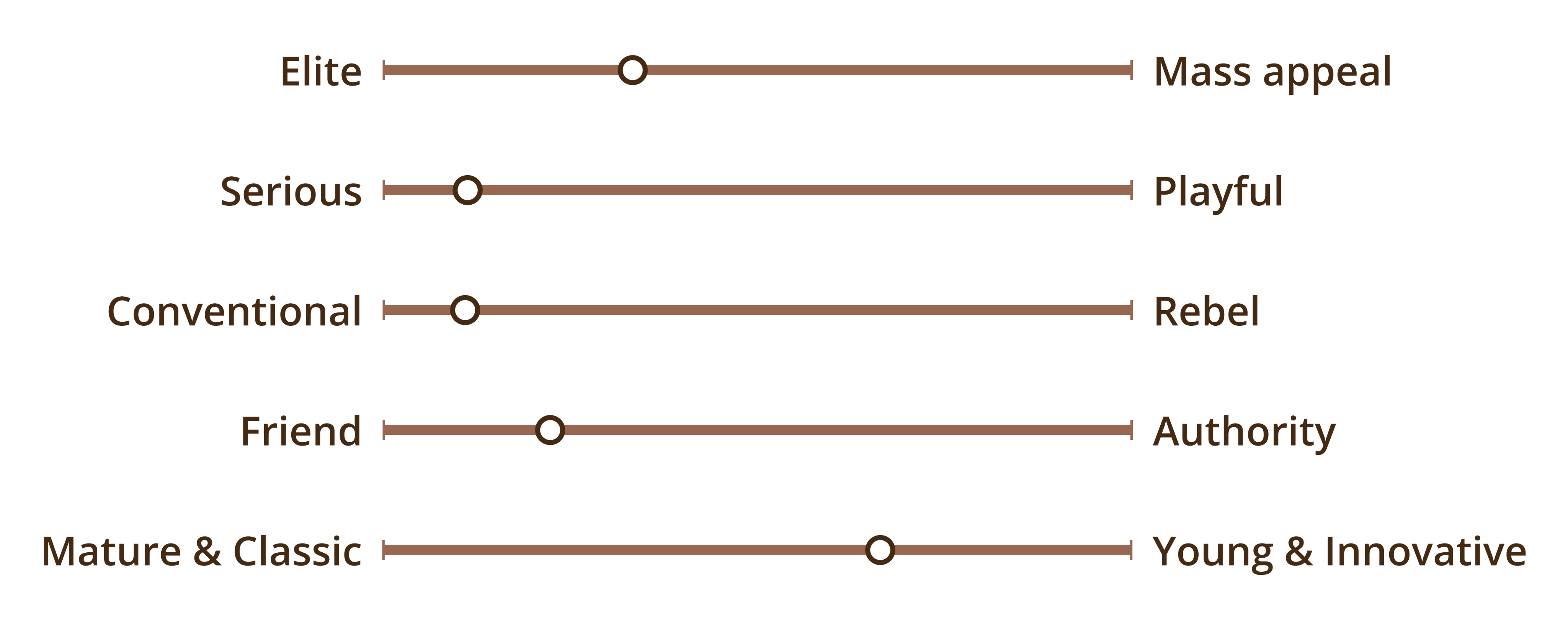
Personality sliders defined the tools´ tone and character, providing a foundation for visual design ideation and guiding decisions regarding form, color and overall style.
Association & Negative Brainstorming: Set a creative tone at the start of the sketching phase, encouraging experimentation, uncovering unusual ideas, reducing pressure to deliver fully formed solutions.
King
Wheel
Stone block
Hallway
Honest
Water
Coincil
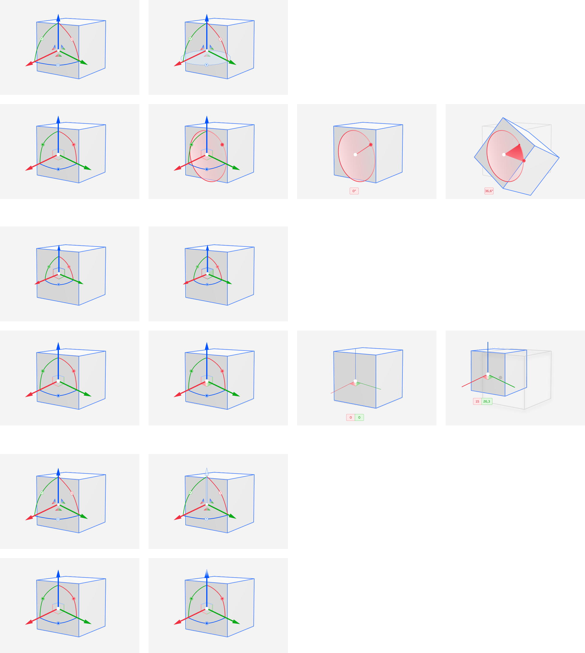
Rapid prototyping: Essential for evaluating abstract 3D interaction concepts; lightweight prototypes simulated behavior, tested assumptions, and uncovered failure points, while identifying promising concepts for iterative refinement through structured critique and prioritization.


Variations in gizmo form and visual appearance testing various combinations along with how to combine all functions in one tool.


Visual rulers and interval markers to improve perception of distance and scale along with hiding part of the tool during active interaction.


Ideas for displaying intervals and scales based on cursor behaviour and user interaction.
Testing and iterating on interaction behaviour and visual feedback for state changes like hover and active states.
Impact:
The sprint resulted in a clear design direction: a unified 3D gizmo that simplifies object manipulation through strong affordance signaling and supportive interaction behaviors. Guiding lines, incremental feedback, and direct value editing emerged as core mechanisms to support both precision and speed, while maintaining visual clarity in complex scenes.
This direction aligned the team around a shared vision and provided a strong foundation for further validation, iteration, and refinement in subsequent design phases.
Concept Creation
- Refined Concepts: Rough concepts from the design sprint were presented to the broader team and evaluated using dot voting, with multiple rounds of iteration narrowing the options to two well-defined concepts.
- Opportunity Re-evaluated: Scaling objects, one feature previously identified as an opportunity (Bud) was discarded. The effort required outweighed the user value, as objects in robot simulation software (e.g., robot models or CAD components) typically have fixed dimensions to match real-world equipment.
- Visual Refinement: Focused on narrowing visual design variations, including colors, shapes, and sizes of main tool elements, to establish a cohesive and usable design direction.
A/B Testing
A user study with A/B testing evaluated the two concepts from Concept Creation. Participants assessed the tools in terms of visual design, functionality, and intuitiveness, focusing on:
- Default appearance
- Hover state behavior
- Active interaction states (translation, rotation, plane translation)
- Selection and use of supporting functions
Prototypes demonstrating the two concepts was presented to the users one by one and they could provide thier feedback
Key Outcomes:
- Determined which concept best meet user needs
- Extracted appreciated features from the less successful concept to enhance the winning design
- Iterated based on user feedback to refine and extend functionality
Impact:
The study validated that users responded positively to the new solution, viewing it as an improvement over the existing tool. Participants particularly appreciated the enhanced visual guidance for direction, incremental movement, and the ability to edit an object’s position directly in the 3D environment using the numeric input. Color variations between concepts had little effect on user preference; instead, users valued a larger tool with more space between elements, which reduced the risk of accidentally interacting with the wrong control. Insights guided refinement of the selected concept and created clear implementation steps for development.
Realization
The final phase focused on supporting development and refining the design during implementation. Because the tool operates in a 3D environment, several aspects of interaction and visual design were difficult to fully anticipate without seeing and using the gizmo in context.
Development support
Design artifacts were translated into actionable implementation steps, including:
- Detailed specifications for interaction behaviors (translation, rotation, plane translation, supporting functions).
- Annotated visual designs, covering colors, shapes, sizes, and spacing of gizmo elements.
- Prototypes and documentation clarifying dynamic states, hover effects, and feedback mechanisms.
- Guidance for consistent behavior across desktop and web platforms.
As the tool was implemented in both a web environment and a desktop product, specific adjustments were made for each platform to account for differences in 3D rendering capabilities and performance.
Active collaboration with development ensured design intent was preserved while accommodating technical constraints.
Key Iteration Areas
- Color Usage: Colors behaved differently in the real environment then in static designs, affected by background, nearby objects, and lighting. Brightness and opacity required hands-on adjustment to balance visibility and visual noise.
- Accessibility: Conventional red, green, and blue axes posed challenges for color-blind users. Axes were differentiated not only by hue but also by saturation, ensuring sufficient contrast across varying scene conditions.
- Size and Scaling: Gizmo dimensions were adjusted based on firsthand interaction. Sizes that looked appropriate in design did not always feel natural during use, especially across different camera distances.
- Supporting Features: Rulers for incremental movement evolved during development. Initial assumptions about scale and step size proved insufficient, and automatic adaptation to cursor speed did not provide a smooth experience. Instead, movement increments are activated via keyboard shortcuts, giving users precise control on demand. This approach balances fast and precise translation, supports different user skill levels, and avoids introducing default behavior that could confuse first-time users. The result is a more intuitive and flexible manipulation experience aligned with users’ spatial context.
Internal Testing
Internal testing validated the functionality of the new gizmo tool and ensured it was intuitive for first-time users. Focus areas included:
- Ease of understanding and efficiency across simple and complex scene layouts.
- Interaction quality, including responsiveness, visual feedback, and smoothness of manipulation.
- How quickly users could grasp the interaction model and perform tasks without friction or unintended behavior.
Testing confirmed that the core interaction felt reliable and predictable, providing the necessary functionality to efficiently manipulate 3D objects within robot simulation software.
Impact
Iterative refinements during development and internal testing ensured the final tool was usable, accessible, and responsive within the 3D environment. Users responded positively to the new solution, seeing it as an improvement over the previous tool. They particularly valued:
- Enhanced visual guidance for direction and incremental movement.
- Ability to edit positions directly via numeric input.
- Larger tool size with more spacing between elements, reducing accidental interactions.
- Color variations were less significant to users than these usability improvements.
These adjustments enhanced precision, learnability, and overall user satisfaction, delivering a tool that met the needs of both novice and expert users across desktop and web platforms.
Outcome
New Gizmo Tool
The project resulted in a new combined gizmo that enables users to efficiently move and rotate 3D objects within a graphical environment, with both speed and precision. By merging move and rotate functionality into a single tool, the design reduced the need for mode switching and unnecessary clicks, an important improvement given that these actions are frequently used together when assembling layouts for robotic automation cells.
In addition to core manipulation, the new gizmo introduced supporting functions designed to improve control, precision, and ease of use. These included rulers, activated via keyboard input, allowing users to move objects in defined increments along an active axis. To further support precision, a numeric input field appears during translation and rotation, displaying the current real time coordinate value and enabling users to enter exact values directly. This allowed users to fluidly switch between free manipulation and precise, value-based adjustments without breaking their workflow.
A key design goal was to improve feedback and predictability to reduce unintended errors. Hover states clearly indicate which parts of the gizmo are interactive and what type of manipulation each element supports. To further support spatial understanding in a 3D environment, the gizmo displays guiding axis lines and visualizes the delta between the object’s starting position and its current position during manipulation. This helped users better understand the consequences of their actions before completing them, an especially important improvement given the cognitive demands of working in a complex spatial environment.
Observations and insights from early research suggested that existing manipulation tools could be improved in terms of clarity, feedback, and control. The new gizmo directly addressed these issues by offering a clearer interaction model, stronger visual cues, and more precise control mechanisms.
Following release, the gizmo led to measurable improvements in efficiency and user satisfaction. Many users shifted from relying primarily on control panels with numeric input fields for precise positioning of 3D objects to using the gizmo as their primary method for manipulation. Command statistics confirmed widespread adoption, with the gizmo activated in the majority of new sessions. In post-release user research sessions, the tool was frequently highlighted as a valued part of the application, demonstrating that it successfully met user needs, improved the early stages of the 3D layout workflow, and reduced overall frustration with the software.
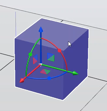
Default
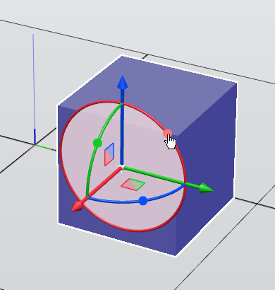
Hover
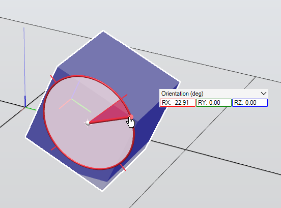
Rotate around X-axis
(Click and drag)(*hold shift to move with precision)
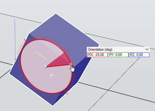
Rotate with increments, 5 deg
(hold ctrl while dragging)
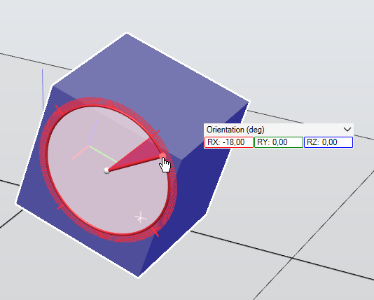
Rotate with fine increments, 1 deg
(hold ctrl + shift while dragging)
Other functionality for increased user flexibility
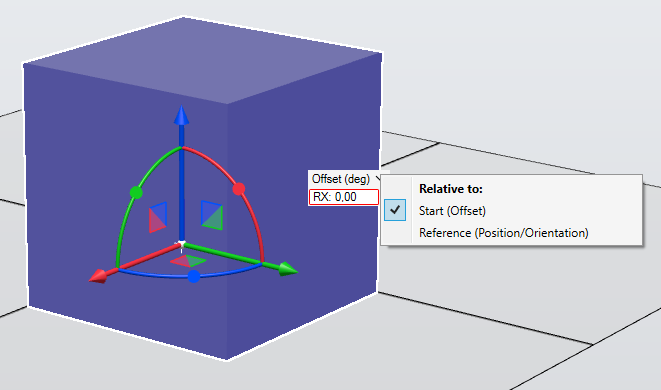
The user can choose to view the offset values of the movement, meaning the delta from the start position to the new position, or the absolute position, meaning the exact reference coordinate system value. This provides flexibility and use case adaptation.
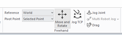
Users can toggle the move and rotate tool on/off in the application toolbar. One button, one tool = less navigation.
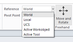
Users can change the reference coordinate system to align with. Aligns tool with context of use.
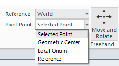
Users can change pivot point the tool should align with affecting where on the object it is displayed. Extended user control.
Main Takeaways
- Understand the domain and use caseFeatures should address real user needs and improve workflow without overcomplicating the interface. Striking the right balance between smart functionality and simplicity is critical.
- Test early and often, especially designing for 3D environmentsSome design aspects cannot be fully anticipated without hands-on testing. Observing users interacting with the tool revealed nuances that were difficult to imagine during conceptualization.
- Leave room for innovationAvoid becoming too restrictive too early. Exploring ideas without immediate concern for feasibility allows initially unrealistic concepts to become viable solutions when refined and concretized.

Gizmo
A tool for manipulating object in a 3D environment.
ABB ROBOTICS
Research
UX
UI
User Testing
Gizmo
A tool for manipulating object in a 3D environment.
ABB ROBOTICS
Research
UX
UI
User Testing
View Case Study

Goal:
Redesign the 3D manipulation experience in robot simulation software to balance precision, speed, and learnability for both novice and expert users working in complex spatial environments.
Outcome:
The new 3D gizmo tool was shipped across both desktop and web platforms, aligning interaction patterns and delivering a consistent experience for robot programmers, resulting in improved efficiency and user satisfaction.
My Role
Led end-to-end UX for redesigning the 3D manipulation experience, from research and concept definition through usability testing, final design, and engineering implementation support.
Tool & Process
- Figma Design: UI design and interactive prototyping.
- Design Sprint: Ideation, problem framing, and concept development.
- SAFe Methodology: Agile project execution through prioritized, task-based iterative development.
Overview
Project Aim
Understand how robot programmers interact with 3D objects in a graphical environment to support both rapid layout creation and precise positioning of targets and paths, while ensuring they feel supported, confident, and in control.
Key Design Challenges
- Enabling robot programmers to manipulate 3D objects with confidence and a strong sense of control.
- Improving precision and efficiency without increasing interaction complexity.
- Supporting expert workflows while keeping the learning curve low for new users.
Process


Sections
Click to navigate →
Research
Understanding use cases and current situation
The first step in the process was to evaluate the current tools and understand users’ existing workflows and pain points.
This included:
- Hands-on testing: interacting with 3D objects in the graphic environment using the current tools to experience usability first-hand.
- User interviews: speaking with robot programmers to gather their perspectives on the existing interaction model.
The original tool
The original 3D manipulation experience presented two tool variations, one for translation and one for rotation. The user could switch between these in the application toolbar using two buttons, when using these two functions in parallel it meant shifting focus and moving the cursor back end forth between the object and the toggle buttons.
The only affordance showing that the tool can be interacted with is displayed when the cursor changes to a hand on hover.
There is a indicator showing the values of the coordinate positions for X, Y and Z axes but there are no guidance to which coordinate belongs to which tool axis and when all 3 axes values are shown independent off which axis the user is currently interacting with it can lead to confusion and errors.
The rotation behavior is quite unexpected as it rotates the object around the world coordinate system zero point and not the objects own center point.
User Perspective
The Robot Programmer
I usually start with a rough layout to understand how the robot should be positioned in relation to the workpiece inside the cell. Getting the reach, angles, and accessibility right early on saves a lot of time later. Once I move into programming, precision becomes critical. The robot has to handle parts with high repeatability, and when it comes to welding, tolerances are tight so even small deviations can affect quality
Positioning objects is the 3D environment is part of by daily work.
When starting a new project I need to find a layout that works for the automation application I am building.
Defining the layout of a robot cell often requires several iterations, it is important that the robot can reach all parts of the work station to preform its task.
The demand for precise positioning is high, it often comes down to millimetres.
The objects you need to position is of course the robot, conveyors and other machines included in the station, but also the points (targets) in the path the robot moves along to perform work.
Key Insights / Pain Points:
- Users felt restricted and inefficient because moving and rotating objects required switching between two separate tools, which is tiresome when performing combined actions multiple times.
- The existing tools provided very little feedback, making it difficult to anticipate which axis an object would move along, leading to errors.
- The rotation tool behaved unexpectedly, rotating objects around the world coordinate system zero by default instead of the object itself, causing confusion and low adoption.
- Users lacked control and precision, forcing them to roughly position objects in the graphical interface and then rely on a control panel to set exact coordinates or distances for each axis.
Impact:
These issues made the 3D manipulation experience slow, error-prone, and frustrating, reducing overall efficiency and confidence in the workflow.
Benchmark
As a second step to inform the design, 3D manipulation tools from robot simulation, CAD, and 3D modeling software were evaluated to identify their strengths, weaknesses, and interaction conventions.
Domains evaluated:
- Robot simulation software: To understand industry-specific workflows and requirements.
- CAD and 3D modeling software: Recognized for precision and expertlevel 3D manipulation.
- Architectural tools and games: Known for intuitive, efficient layout and assembly interactions.
Key Outcomes / Insights:
- Created a benchmark comparison of 3D manipulation tools across robot simulation, CAD, and 3D modeling software, highlighting strengths, weaknesses, notable features, and design opportunities.
- Identified common conventions such as frequently used functions, interaction patterns, and keyboard shortcuts that users expect across 3D environments.
- Extracted transferable patterns and principles that could be adapted to improve efficiency, precision, and learnability for robot programmers.
- Evaluated visual and interaction affordances of manipulation tools, recognizing that shape, color, size, and placement play a critical role in communicating how a tool should be used and interacted with.
Example of findings from benchmark comparison:
- Tool structure: Single vs. combined manipulation toolsSome software separates translation, rotation, and scaling into three distinct tools, each activated by a dedicated button. This approach reduces complexity per tool but requires more clicks to changes between the tools. Others softwares combine translation, rotation, and scaling into a single tool activated with one button, reducing amount of clicks but potentially increasing visual complexity and cognitive load.
Individual transform tools for translate, rotate, and scale.
Image source: Unity
All-in-one translation, rotation and scaling tool.
Image source: Adobe Dimensions
- Visual appearance: Impact on perceptionLarge differences in the portrayed feeling of the gizmo tool depending on line thickness and color nuances and saturation making some fell more childish and playful while others came across like more serious and professional. This is an aspect to consider to make the 3D manipulation tool fit the context of use, for example in a game engine or in a professional 3D modeling tool.
Saturated colors and thick lines signals more playfulness.
Image source: Unreal Engine.
Soft colors slim lines signals more seriousness.
Image source: Autodesk Inventor
- New functions: Plane-based translation and scaling.Many tools presented an option to translate an object along a plane, meaning along a two-dimensional surface involving two axes at the same time, as well as functionality to scale an object. These were non-existing functions in our 3D object manipulation experience, raising the question of whether including them in the redesign would bring value.
Plane-based translation
Image source: Unreal Engine, Adobe Dimension and Autodesk inventor.
Scale
Image source: Unreal Engine, Adobe Dimension and Autodesk inventor.
- Affordances and interaction statesMost evaluated tools provided strong visual affordances through distinct interaction states, including default, hover, and active. These state changes helped communicate interactivity, clarified which control was currently engaged, and reinforced user confidence during manipulation.
Clear differences between default, hover and active state.
Image source: Adobe Dimensions
Clear differences between default, hover and active state.
Image source: Autodesk Fusion 360
- Supporting functions and guidance It was common for 3D manipulation tools to present supporting functions, such as rulers and numeric values, in the active state to help users understand how much they had translated the object and to support precise movements.
Supporting rulers with increments.
Image source: Sketchup
Image source: SolidWorks
Numeric value displayed and editable.
Image source: Autodesk Fusion 360
- Cross-Interaction Inspiration: Adaptive SpeedOpportunities were identified by examining interactions beyond direct object manipulation. For example, in some tools, viewport zoom speed adapts based on distance to the target: zooming is faster when far away and slows as the camera approaches the object, allowing for fine-tuned control. This adaptive speed behavior suggested a potential interaction pattern that could be translated to object manipulation, where movement speed dynamically adjusts based on context to balance efficiency and precision.
Impact:
The benchmark identified familiar conventions and transferable patterns, providing evidence-based guidance to design a 3D manipulation system that balances precision, efficiency, and learnability.
Literature Review
As part of the research phase, existing literature and prior work on 3D interaction and object manipulation were reviewed to identify best practices and domain conventions relevant to designing the new 3D manipulation tool. The review focused on how users interact with 3D objects, common interface conventions, and strategies to support both novice and expert users.
Key Findings:
- Axis conventions: Standard color coding for translation along axes (red = X, green = Y, blue = Z), helps users quickly understand movement direction and reduces cognitive load. This convention is widely adopted across 3D software, providing users with a familiar interaction model.
- Movement constraints: Allowing objects to also be move along a plane (e.g., a “floor” or “wall”) can make spatial manipulation more intuitive and efficient, especially for tasks aligned with real-world surfaces.
- Mental models: Users generally expect objects to move and rotate relative to their center of gravity, but providing the option to adjust the manipulation pivot (e.g., to an edge or corner) supports precise placement and alternative workflows. Aligning interaction tools with users’ mental models increases predictability and reduces errors.
Impact:
These findings informed the visual design, interaction constraints, and user expectations for the new 3D manipulation tool. By following established conventions, the interface feels familiar to users with prior experience in 3D software, while also incorporating enhancements to improve precision, learnability, and flexibility for complex tasks.
Design
Design Sprint
The design phase started with a focused 3-day design sprint to explore alternatives and clarify a viable direction for 3D object manipulation in a spatial environment where the existing tool lacked clear affordances and created friction during precision tasks.
Rather than aiming for a single polished solution, the sprint was exploratory, focusing on uncovering opportunities, testing assumptions, and understanding how different interaction models might support both novice and expert workflows. The design sprint format was chosen to quickly define a direction and evaluate ideas in the context of a complex interaction problem.
Process and Methods:
Problem Framing
Expert interviews
User journey mapping
Rose, Thorn, Bud
How might we
Understand & Define
Success matrix and signals
Personality sliders
Golden path
Sketch
Association exercises
Negative brainstorming
Crazy 8’s
Morphological chart
Decide
Art museum
Heat map
Speed critique
Straw pull & Supervote
Create concept
Prototype
Storyboard
Rapid prototyping
Sprint planned with inspiration from Google Design Sprint kit.
Design Focus Areas:
Interaction Behavior
The existing manipulation tool provided limited guidance, which created friction for users working with precision in complex 3D scenes. Exploration during the sprint focused on identifying interaction behaviors that could better support user intent while avoiding unnecessary complexity.
Areas of focus included:
- Improving affordance clarity during manipulation.
- Supporting both coarse and fine-grained adjustments.
- Reducing accidental or unintended movements.
- Providing clearer feedback during active interactions.
Key Exploration Areas:
The sprint explored a range of interaction and visual strategies, including:
- Pairing direct manipulation with real-time numeric input to support precision without breaking flow.
- Adaptive movement speed based on cursor behavior and interaction intent.
- Visual rulers and interval markers to improve perception of distance and scale.
- Variations in gizmo form, color saturation, and visual weight to assess perceived precision and trust.
- Unified manipulation tool combining translation, rotation, and related functions.
- Interaction feedback including hover states and reduced visual noise during active manipulation.
Key Methods:
Rose, Thorn, Bud: Identified positive, negative and opportunity areas in the original tool, aligning the team on what to retain, improve or reimagine.
Rose
- Uses conventional cartesian coordinate colors for X, Y, Z axes.
- Large tool size reduces risk of accidentally grabbing the wrong function.
Thorn
- Need to use button to switch translation type (move, rotate).
- All parts of the tool still visible in active state.
- Not clear how much an object is being translated to its new position.
Bud
- Having one tool with all functionality makes operation more effective.
- Increase affordance on hover.
- Hide all parts of the tool in active state except the active function.
- Allow user to scale objects.
- Introduce movement along a plane for easy translating along “real life” surfaces like a table or along the floor.
Personality sliders defined the tools´ tone and character, providing a foundation for visual design ideation and guiding decisions regarding form, color and overall style.
Association & Negative Brainstorming: Set a creative tone at the start of the sketching phase, encouraging experimentation, uncovering unusual ideas, reducing pressure to deliver fully formed solutions.
King
Wheel
Stone block
Hallway
Honest
Water
Coincil
Rapid prototyping: Essential for evaluating abstract 3D interaction concepts; lightweight prototypes simulated behavior, tested assumptions, and uncovered failure points, while identifying promising concepts for iterative refinement through structured critique and prioritization.


Variations in gizmo form and visual appearance testing various combinations along with how to combine all functions in one tool.


Visual rulers and interval markers to improve perception of distance and scale along with hiding part of the tool during active interaction.
Testing ideas for displaying intervals/scales based on cursor behaviour and user interaction.
Testing and iterating on interaction behaviour and visual feedback for state changes like hover and active states.
Impact:
The sprint resulted in a clear design direction: a unified 3D gizmo that simplifies object manipulation through strong affordance signaling and supportive interaction behaviors. Guiding lines, incremental feedback, and direct value editing emerged as core mechanisms to support both precision and speed, while maintaining visual clarity in complex scenes.
This direction aligned the team around a shared vision and provided a strong foundation for further validation, iteration, and refinement in subsequent design phases.
Concept Creation
- Refined Concepts: Rough concepts from the design sprint were presented to the broader team and evaluated using dot voting, with multiple rounds of iteration narrowing the options to two well-defined concepts.
- Opportunity Re-evaluated: Scaling objects, one feature previously identified as an opportunity (Bud) was discarded. The effort required outweighed the user value, as objects in robot simulation software (e.g., robot models or CAD components) typically have fixed dimensions to match real-world equipment.
- Visual Refinement: Focused on narrowing visual design variations, including colors, shapes, and sizes of main tool elements, to establish a cohesive and usable design direction.
A/B Testing
A user study with A/B testing evaluated the two concepts from Concept Creation. Participants assessed the tools in terms of visual design, functionality, and intuitiveness, focusing on:
- Default appearance
- Hover state behavior
- Active interaction states (translation, rotation, plane translation)
- Selection and use of supporting functions
Prototypes demonstrating the two concepts was presented to the users one by one and they could provide thier feedback
Key Outcomes:
- Determined which concept best meet user needs
- Extracted appreciated features from the less successful concept to enhance the winning design
- Iterated based on user feedback to refine and extend functionality
Impact:
The study validated that users responded positively to the new solution, viewing it as an improvement over the existing tool. Participants particularly appreciated the enhanced visual guidance for direction, incremental movement, and the ability to edit an object’s position directly in the 3D environment using the numeric input. Color variations between concepts had little effect on user preference; instead, users valued a larger tool with more space between elements, which reduced the risk of accidentally interacting with the wrong control. Insights guided refinement of the selected concept and created clear implementation steps for development.
Realization
The final phase focused on supporting development and refining the design during implementation. Because the tool operates in a 3D environment, several aspects of interaction and visual design were difficult to fully anticipate without seeing and using the gizmo in context.
Development support
Design artefacts were translated into actionable implementation steps, including:
- Detailed specifications for interaction behaviors (translation, rotation, plane translation, supporting functions).
- Annotated visual designs, covering colors, shapes, sizes, and spacing of gizmo elements.
- Prototypes and documentation clarifying dynamic states, hover effects, and feedback mechanisms.
- Guidance for consistent behavior across desktop and web platforms.
As the tool was implemented in both a web environment and a desktop product, specific adjustments were made for each platform to account for differences in 3D rendering capabilities and performance.
Active collaboration with development ensured design intent was preserved while accommodating technical constraints.
Key Iteration Areas
- Color Usage: Colors behaved differently in the real environment then in static designs, affected by background, nearby objects, and lighting. Brightness and opacity required hands-on adjustment to balance visibility and visual noise.
- Accessibility: Conventional red, green, and blue axes posed challenges for color-blind users. Axes were differentiated not only by hue but also by saturation, ensuring sufficient contrast across varying scene conditions.
- Size and Scaling: Gizmo dimensions were adjusted based on firsthand interaction. Sizes that looked appropriate in design did not always feel natural during use, especially across different camera distances.
- Supporting Features: Rulers for incremental movement evolved during development. Initial assumptions about scale and step size proved insufficient, and automatic adaptation to cursor speed did not provide a smooth experience. Instead, movement increments are activated via keyboard shortcuts, giving users precise control on demand. This approach balances fast and precise translation, supports different user skill levels, and avoids introducing default behavior that could confuse first-time users. The result is a more intuitive and flexible manipulation experience aligned with users’ spatial context.
Internal Testing
Internal testing validated the functionality of the new gizmo tool and ensured it was intuitive for first-time users. Focus areas included:
- Ease of understanding and efficiency across simple and complex scene layouts.
- Interaction quality, including responsiveness, visual feedback, and smoothness of manipulation.
- How quickly users could grasp the interaction model and perform tasks without friction or unintended behavior.
Testing confirmed that the core interaction felt reliable and predictable, providing the necessary functionality to efficiently manipulate 3D objects within robot simulation software.
Impact
Iterative refinements during development and internal testing ensured the final tool was usable, accessible, and responsive within the 3D environment. Users responded positively to the new solution, seeing it as an improvement over the previous tool. They particularly valued:
- Enhanced visual guidance for direction and incremental movement.
- Ability to edit positions directly via numeric input.
- Larger tool size with more spacing between elements, reducing accidental interactions.
- Color variations were less significant to users than these usability improvements.
These adjustments enhanced precision, learnability, and overall user satisfaction, delivering a tool that met the needs of both novice and expert users across desktop and web platforms.
Outcome
New Gizmo Tool
The project resulted in a new combined gizmo that enables users to efficiently move and rotate 3D objects within a graphical environment, with both speed and precision. By merging move and rotate functionality into a single tool, the design reduced the need for mode switching and unnecessary clicks, an important improvement given that these actions are frequently used together when assembling layouts for robotic automation cells.
In addition to core manipulation, the new gizmo introduced supporting functions designed to improve control, precision, and ease of use. These included rulers, activated via keyboard input, allowing users to move objects in defined increments along an active axis. To further support precision, a numeric input field appears during translation and rotation, displaying the current real time coordinate value and enabling users to enter exact values directly. This allowed users to fluidly switch between free manipulation and precise, value-based adjustments without breaking their workflow.
A key design goal was to improve feedback and predictability to reduce unintended errors. Hover states clearly indicate which parts of the gizmo are interactive and what type of manipulation each element supports. To further support spatial understanding in a 3D environment, the gizmo displays guiding axis lines and visualizes the delta between the object’s starting position and its current position during manipulation. This helped users better understand the consequences of their actions before completing them, an especially important improvement given the cognitive demands of working in a complex spatial environment.
Observations and insights from early research suggested that existing manipulation tools could be improved in terms of clarity, feedback, and control. The new gizmo directly addressed these issues by offering a clearer interaction model, stronger visual cues, and more precise control mechanisms.
Following release, the gizmo led to measurable improvements in efficiency and user satisfaction. Many users shifted from relying primarily on control panels with numeric input fields for precise positioning of 3D objects to using the gizmo as their primary method for manipulation. Command statistics confirmed widespread adoption, with the gizmo activated in the majority of new sessions. In post-release user research sessions, the tool was frequently highlighted as a valued part of the application, demonstrating that it successfully met user needs, improved the early stages of the 3D layout workflow, and reduced overall frustration with the software.
Default
Hover
Rotate around X-axis
(Click and drag)(*hold shift to move with precision)
Rotate with increments, 5 deg
(hold ctrl while dragging)
Rotate with fine increments, 1 deg
(hold ctrl + shift while dragging)
Other functionality for increased user flexibility
The user can choose to view the offset values of the movement, meaning the delta from the start position to the new position, or the absolute position, meaning the exact reference coordinate system value. This provides flexibility and use case adaptation.
Users can toggle the move and rotate tool on/off in the application toolbar. One button, one tool = less navigation.
Users can change the reference coordinate system to align with. Aligns tool with context of use.
Users can change pivot point the tool should align with affecting where on the object it is displayed. Extended user control.
Main Takeaways
- Understand the domain and use caseFeatures should address real user needs and improve workflow without overcomplicating the interface. Striking the right balance between smart functionality and simplicity is critical.
- Test early and often, especially designing for 3D environmentsSome design aspects cannot be fully anticipated without hands-on testing. Observing users interacting with the tool revealed nuances that were difficult to imagine during conceptualization.
- Leave room for innovationAvoid becoming too restrictive too early. Exploring ideas without immediate concern for feasibility allows initially unrealistic concepts to become viable solutions when refined and concretized.
Gizmo
A tool for manipulating object in a 3D environment.
ABB ROBOTICS
Research
UX
UI
User Testing
Goal:
Redesign the 3D manipulation experience in robot simulation software to balance precision, speed, and learnability for both novice and expert users working in complex spatial environments.
Outcome:
The new 3D gizmo tool was shipped across both desktop and web platforms, aligning interaction patterns and delivering a consistent experience for robot programmers, resulting in improved efficiency and user satisfaction.
My Role
Led end-to-end UX for redesigning the 3D manipulation experience, from research and concept definition through usability testing, final design, and engineering implementation support.
Tool & Process
- Figma Design: UI design and interactive prototyping.
- Design Sprint: Ideation, problem framing, and concept development.
- SAFe Methodology: Agile project execution through prioritized, task-based iterative development.
Overview
Project Aim
Understand how robot programmers interact with 3D objects in a graphical environment to support both rapid layout creation and precise positioning of targets and paths, while ensuring they feel supported, confident, and in control.
Key Design Challenges
- Enabling robot programmers to manipulate 3D objects with confidence and a strong sense of control.
- Improving precision and efficiency without increasing interaction complexity.
- Supporting expert workflows while keeping the learning curve low for new users.
Process

Sections
Click to navigate →
Research
Understanding use cases and current situation
The first step in the process was to evaluate the current tools and understand users’ existing workflows and pain points.
This included:
- Hands-on testing: interacting with 3D objects in the graphic environment using the current tools to experience usability first-hand.
- User interviews: speaking with robot programmers to gather their perspectives on the existing interaction model.
The original tool
The original 3D manipulation experience presented two tool variations, one for translation and one for rotation. The user could switch between these in the application toolbar using two buttons, when using these two functions in parallel it meant shifting focus and moving the cursor back end forth between the object and the toggle buttons.
The only affordance showing that the tool can be interacted with is displayed when the cursor changes to a hand on hover.
There is a indicator showing the values of the coordinate positions for X, Y and Z axes but there are no guidance to which coordinate belongs to which tool axis and when all 3 axes values are shown independent off which axis the user is currently interacting with it can lead to confusion and errors.
The rotation behavior is quite unexpected as it rotates the object around the world coordinate system zero point and not the objects own center point.
User Perspective
The Robot Programmer
I usually start with a rough layout to understand how the robot should be positioned in relation to the workpiece inside the cell. Getting the reach, angles, and accessibility right early on saves a lot of time later. Once I move into programming, precision becomes critical. The robot has to handle parts with high repeatability, and when it comes to welding, tolerances are tight so even small deviations can affect quality
Positioning objects is the 3D environment is part of by daily work.
When starting a new project I need to find a layout that works for the automation application I am building.
Defining the layout of a robot cell often requires several iterations, it is important that the robot can reach all parts of the work station to preform its task.
The demand for precise positioning is high, it often comes down to millimetres.
The objects you need to position is of course the robot, conveyors and other machines included in the station, but also the points (targets) in the path the robot moves along to perform work.
Key Insights / Pain Points:
- Users felt restricted and inefficient because moving and rotating objects required switching between two separate tools, which is tiresome when performing combined actions multiple times.
- The existing tools provided very little feedback, making it difficult to anticipate which axis an object would move along, leading to errors.
- The rotation tool behaved unexpectedly, rotating objects around the world coordinate system zero by default instead of the object itself, causing confusion and low adoption.
- Users lacked control and precision, forcing them to roughly position objects in the graphical interface and then rely on a control panel to set exact coordinates or distances for each axis.
Impact:
These issues made the 3D manipulation experience slow, error-prone, and frustrating, reducing overall efficiency and confidence in the workflow.
Benchmark
As a second step to inform the design, 3D manipulation tools from robot simulation, CAD, and 3D modeling software were evaluated to identify their strengths, weaknesses, and interaction conventions.
Domains evaluated:
- Robot simulation software: To understand industry-specific workflows and requirements.
- CAD and 3D modeling software: Recognized for precision and expert-level 3D manipulation.
- Architectural tools and games: Known for intuitive, efficient layout and assembly interactions.
Key Outcomes / Insights:
- Created a benchmark comparison of 3D manipulation tools across robot simulation, CAD, and 3D modeling software, highlighting strengths, weaknesses, notable features, and design opportunities.
- Identified common conventions such as frequently used functions, interaction patterns, and keyboard shortcuts that users expect across 3D environments.
- Extracted transferable patterns and principles that could be adapted to improve efficiency, precision, and learnability for robot programmers.
- Evaluated visual and interaction affordances of manipulation tools, recognizing that shape, color, size, and placement play a critical role in communicating how a tool should be used and interacted with.
Example of findings from benchmark comparison:
- Tool structure: Single vs. combined manipulation toolsSome software separates translation, rotation, and scaling into three distinct tools, each activated by a dedicated button. This approach reduces complexity per tool but requires more clicks to changes between the tools. Others softwares combine translation, rotation, and scaling into a single tool activated with one button, reducing amount of clicks but potentially increasing visual complexity and cognitive load.
Individual transform tools for translate, rotate, and scale.
Image source: Unity
All-in-one translation, rotation and scaling tool.
Image source: Adobe Dimensions
- Visual appearance: Impact on perceptionLarge differences in the portrayed feeling of the gizmo tool depending on line thickness and color nuances and saturation making some fell more childish and playful while others came across like more serious and professional. This is an aspect to consider to make the 3D manipulation tool fit the context of use, for example in a game engine or in a professional 3D modeling tool.
Saturated colors and thick lines signals more playfulness.
Image source: Unreal Engine.
Soft colors slim lines signals more seriousness.
Image source: Autodesk Inventor
- New functions: Plane-based translation and scaling.Many tools presented an option to translate an object along a plane, meaning along a two-dimensional surface involving two axes at the same time, as well as functionality to scale an object. These were non-existing functions in our current 3D object manipulation experience, raising the question of whether including them in the redesign would bring value.
Plane-based translation
Image source: Unreal Engine, Adobe Dimension and Autodesk inventor.
Scale
Image source: Unreal Engine, Adobe Dimension and Autodesk inventor.
- Affordances and interaction statesMost evaluated tools provided strong visual affordances through distinct interaction states, including default, hover and active. These state changes helped communicate interactivity, clarified which control was currently engaged, and reinforced user confidence during manipulation.
Clear differences between default, hover and active state.
Image source: Adobe Dimensions
Clear differences between default, hover and active state.
Image source: Autodesk Fusion 360
- Supporting functions and guidance It was common for 3D manipulation tools to present supporting functions, such as rulers and numeric values, in the active state to help users understand how much they had translated the object and to support precise movements.
Supporting rulers with increments.
Image source: Sketchup
Image source: SolidWorks
Numeric value displayed and editable.
Image source: Autodesk Fusion 360
- Cross-Interaction Inspiration: Adaptive SpeedOpportunities were identified by examining interactions beyond direct object manipulation. For example, in some tools, viewport zoom speed adapts based on distance to the target: zooming is faster when far away and slows as the camera approaches the object, allowing for fine-tuned control. This adaptive speed behavior suggested a potential interaction pattern that could be translated to object manipulation, where movement speed dynamically adjusts based on context to balance efficiency and precision.
Impact:
The benchmark identified familiar conventions and transferable patterns, providing evidence-based guidance to design a 3D manipulation system that balances precision, efficiency, and learnability.
Literature Review
As part of the research phase, existing literature and prior work on 3D interaction and object manipulation were reviewed to identify best practices and domain conventions relevant to designing the new 3D manipulation tool. The review focused on how users interact with 3D objects, common interface conventions, and strategies to support both novice and expert users.
Key Findings:
- Axis conventions: Standard color coding for translation along axes (red = X, green = Y, blue = Z), helps users quickly understand movement direction and reduces cognitive load. This convention is widely adopted across 3D software, providing users with a familiar interaction model.
- Movement constraints: Allowing objects to also be move along a plane (e.g., a “floor” or “wall”) can make spatial manipulation more intuitive and efficient, especially for tasks aligned with real-world surfaces.
- Mental models: Users generally expect objects to move and rotate relative to their center of gravity, but providing the option to adjust the manipulation pivot (e.g., to an edge or corner) supports precise placement and alternative workflows. Aligning interaction tools with users’ mental models increases predictability and reduces errors.
Impact:
These findings informed the visual design, interaction constraints, and user expectations for the new 3D manipulation tool. By following established conventions, the interface feels familiar to users with prior experience in 3D software, while also incorporating enhancements to improve precision, learnability, and flexibility for complex tasks.
Design
Design Sprint
The design phase started with a focused 3-day design sprint to explore alternatives and clarify a viable direction for 3D object manipulation in a spatial environment where the existing tool lacked clear affordances and created friction during precision tasks.
Rather than aiming for a single polished solution, the sprint was exploratory, focusing on uncovering opportunities, testing assumptions, and understanding how different interaction models might support both novice and expert workflows. The design sprint format was chosen to quickly define a direction and evaluate ideas in the context of a complex interaction problem.
Process and Methods:
Problem Framing
Expert interviews
User journey mapping
Rose, Thorn, Bud
How might we
Understand & Define
Success matrix and signals
Personality sliders
Golden path
Sketch
Association exercises
Negative brainstorming
Crazy 8’s
Morphological chart
Decide
Art museum
Heat map
Speed critique
Straw pull & Supervote
Create concept
Prototype
Storyboard
Rapid prototyping
Sprint planned with inspiration from Google Design Sprint kit.
Design Focus Areas:
Interaction Behavior
The existing manipulation tool provided limited guidance, which created friction for users working with precision in complex 3D scenes. Exploration during the sprint focused on identifying interaction behaviors that could better support user intent while avoiding unnecessary complexity.
Areas of focus included:
- Improving affordance clarity during manipulation.
- Supporting both coarse and fine-grained adjustments.
- Reducing accidental or unintended movements.
- Providing clearer feedback during active interactions.
Key Exploration Areas:
The sprint explored a range of interaction and visual strategies, including:
- Pairing direct manipulation with real-time numeric input to support precision without breaking flow.
- Adaptive movement speed based on cursor behavior and interaction intent.
- Visual rulers and interval markers to improve perception of distance and scale.
- Variations in gizmo form, color saturation, and visual weight to assess perceived precision and trust.
- Unified manipulation tool combining translation, rotation, and related functions.
- Interaction feedback including hover states and reduced visual noise during active manipulation.
Key Methods:
Rose, Thorn, Bud: Identified positive, negative and opportunity areas in the original tool, aligning the team on what to retain, improve or reimagine.
Rose
- Uses conventional cartesian coordinate colors for X, Y, Z axes.
- Large tool size reduces risk of accidentally grabbing the wrong function.
Thorn
- Need to use button to switch translation type (move, rotate).
- All parts of the tool still visible in active state.
- Not clear how much an object is being translated to its new position.
Bud
- Having one tool with all functionality makes operation more effective.
- Increase affordance on hover.
- Hide all parts of the tool in active state exept the active function.
- Allow user to scale objects.
- Introduce movement along a plane for easy translating along “real life” surfaces like a table or along the floor.
Personality sliders defined the tools´ tone and character, providing a foundation for visual design ideation and guiding decisions regarding form, color and overall style.
Association & Negative Brainstorming: Set a creative tone at the start of the sketching phase, encouraging experimentation, uncovering unusual ideas, reducing pressure to deliver fully formed solutions.
King
Wheel
Stone block
Hallway
Honest
Water
Scholar
Rapid prototyping: Essential for evaluating abstract 3D interaction concepts; lightweight prototypes simulated behavior, tested assumptions, and uncovered failure points, while identifying promising concepts for iterative refinement through structured critique and prioritization.


Variations in gizmo form and visual appearance testing various combinations along with how to combine all functions in one tool.


Visual rulers and interval markers to improve perception of distance and scale along with hiding part of the tool during active interaction.
Ideas for displaying intervals and scales based on cursor behaviour and user interaction.
Testing and iterating on interaction behaviour and visual feedback for state changes like hover and active states.
Impact:
The sprint resulted in a clear design direction: a unified 3D gizmo that simplifies object manipulation through strong affordance signaling and supportive interaction behaviors. Guiding lines, incremental feedback, and direct value editing emerged as core mechanisms to support both precision and speed, while maintaining visual clarity in complex scenes.
This direction aligned the team around a shared vision and provided a strong foundation for further validation, iteration, and refinement in subsequent design phases.
Concept Creation
- Refined Concepts: Rough concepts from the design sprint were presented to the broader team and evaluated using dot voting, with multiple rounds of iteration narrowing the options to two well-defined concepts.
- Opportunity Re-evaluated: Scaling objects, one feature previously identified as an opportunity (Bud) was discarded. The effort required outweighed the user value, as objects in robot simulation software (e.g., robot models or CAD components) typically have fixed dimensions to match real-world equipment.
- Visual Refinement: Focused on narrowing visual design variations, including colors, shapes, and sizes of main tool elements, to establish a cohesive and usable design direction.
A/B Testing
A user study with A/B testing evaluated the two concepts from Concept Creation. Participants assessed the tools in terms of visual design, functionality, and intuitiveness, focusing on:
- Default appearance
- Hover state behavior
- Active interaction states (translation, rotation, plane translation)
- Selection and use of supporting functions
Prototypes demonstrating the two concepts were presented to participants individually. Initial reactions were documented, followed by additional interview questions to better understand user perceptions and gather detailed thoughts and feedback. Results from all participants were then synthesized, allowing key outcomes and clear next steps to be identified.
Key Outcomes:
- Determined which concept best meet user needs
- Extracted appreciated features from the less successful concept to enhance the winning design
- Iterated based on user feedback to refine and extend functionality
Impact:
The study validated that users responded positively to the new solution, viewing it as an improvement over the existing tool. Participants particularly appreciated the enhanced visual guidance for direction, incremental movement, and the ability to edit an object’s position directly in the 3D environment using the numeric input. Color variations between concepts had little effect on user preference; instead, users valued a larger tool with more space between elements, which reduced the risk of accidentally interacting with the wrong control. Insights guided refinement of the selected concept and created clear implementation steps for development.
Realization
The final phase focused on supporting development and refining the design during implementation. Because the tool operates in a 3D environment, several aspects of interaction and visual design were difficult to fully anticipate without seeing and using the gizmo in context.
Development support
Design artefacts were translated into actionable implementation steps, including:
- Detailed specifications for interaction behaviors (translation, rotation, plane translation, supporting functions).
- Annotated visual designs, covering colors, shapes, sizes, and spacing of gizmo elements.
- Prototypes and documentation clarifying dynamic states, hover effects, and feedback mechanisms.
- Guidance for consistent behavior across desktop and web platforms.
As the tool was implemented in both a web environment and a desktop product, specific adjustments were made for each platform to account for differences in 3D rendering capabilities and performance.
Active collaboration with development ensured design intent was preserved while accommodating technical constraints.
Key Iteration Areas
- Color Usage: Colors behaved differently in the real environment then in static designs, affected by background, nearby objects, and lighting. Brightness and opacity required hands-on adjustment to balance visibility and visual noise.
- Accessibility: Conventional red, green, and blue axes posed challenges for color-blind users. Axes were differentiated not only by hue but also by saturation, ensuring sufficient contrast across varying scene conditions.
- Size and Scaling: Gizmo dimensions were adjusted based on firsthand interaction. Sizes that looked appropriate in design did not always feel natural during use, especially across different camera distances.
- Supporting Features: Rulers for incremental movement evolved during development. Initial assumptions about scale and step size proved insufficient, and automatic adaptation to cursor speed did not provide a smooth experience. Instead, movement increments are activated via keyboard shortcuts, giving users precise control on demand. This approach balances fast and precise translation, supports different user skill levels, and avoids introducing default behavior that could confuse first-time users. The result is a more intuitive and flexible manipulation experience aligned with users’ spatial context.
Internal Testing
Internal testing validated the functionality of the new gizmo tool and ensured it was intuitive for first-time users. Focus areas included:
- Ease of understanding and efficiency across simple and complex scene layouts.
- Interaction quality, including responsiveness, visual feedback, and smoothness of manipulation.
- How quickly users could grasp the interaction model and perform tasks without friction or unintended behavior.
Testing confirmed that the core interaction felt reliable and predictable, providing the necessary functionality to efficiently manipulate 3D objects within robot simulation software.
Impact
Iterative refinements during development and internal testing ensured the final tool was usable, accessible, and responsive within the 3D environment. Users responded positively to the new solution, seeing it as an improvement over the previous tool. They particularly valued:
- Enhanced visual guidance for direction and incremental movement.
- Ability to edit positions directly via numeric input.
- Larger tool size with more spacing between elements, reducing accidental interactions.
- Color variations were less significant to users than these usability improvements.
These adjustments enhanced precision, learnability, and overall user satisfaction, delivering a tool that met the needs of both novice and expert users across desktop and web platforms.
Outcome
New Gizmo Tool
The project resulted in a new combined gizmo that enables users to efficiently move and rotate 3D objects within a graphical environment, with both speed and precision. By merging move and rotate functionality into a single tool, the design reduced the need for mode switching and unnecessary clicks, an important improvement given that these actions are frequently used together when assembling layouts for robotic automation cells.
In addition to core manipulation, the new gizmo introduced supporting functions designed to improve control, precision, and ease of use. These included rulers, activated via keyboard input, allowing users to move objects in defined increments along an active axis. To further support precision, a numeric input field appears during translation and rotation, displaying the current real time coordinate value and enabling users to enter exact values directly. This allowed users to fluidly switch between free manipulation and precise, value-based adjustments without breaking their workflow.
A key design goal was to improve feedback and predictability to reduce unintended errors. Hover states clearly indicate which parts of the gizmo are interactive and what type of manipulation each element supports. To further support spatial understanding in a 3D environment, the gizmo displays guiding axis lines and visualizes the delta between the object’s starting position and its current position during manipulation. This helped users better understand the consequences of their actions before completing them, an especially important improvement given the cognitive demands of working in a complex spatial environment.
Observations and insights from early research suggested that existing manipulation tools could be improved in terms of clarity, feedback, and control. The new gizmo directly addressed these issues by offering a clearer interaction model, stronger visual cues, and more precise control mechanisms.
Following release, the gizmo led to measurable improvements in efficiency and user satisfaction. Many users shifted from relying primarily on control panels with numeric input fields for precise positioning of 3D objects to using the gizmo as their primary method for manipulation. Command statistics confirmed widespread adoption, with the gizmo activated in the majority of new sessions. In post-release user research sessions, the tool was frequently highlighted as a valued part of the application, demonstrating that it successfully met user needs, improved the early stages of the 3D layout workflow, and reduced overall frustration with the software.
Default
Hover
Rotate around X-axis
(Click and drag)(*hold shift to move with precision)
Rotate with increments, 5 deg
(hold ctrl while dragging)
Rotate with fine increments, 1 deg
(hold ctrl + shift while dragging)
Other functionality for increased user flexibility
The user can choose to view the offset values of the movement, meaning the delta from the start position to the new position, or the absolute position, meaning the exact reference coordinate system value. This provides flexibility and use case adaptation.
Users can toggle the move and rotate tool on/off in the application toolbar. One button, one tool = less navigation.
Users can change the reference coordinate system to align with. Aligns tool with context of use.
Users can change pivot point the tool should align with affecting where on the object it is displayed. Extended user control.
Main Takeaways
- Understand the domain and use caseFeatures should address real user needs and improve workflow without overcomplicating the interface. Striking the right balance between smart functionality and simplicity is critical.
- Test early and often, especially designing for 3D environmentsSome design aspects cannot be fully anticipated without hands-on testing. Observing users interacting with the tool revealed nuances that were difficult to imagine during conceptualization.
- Leave room for innovationAvoid becoming too restrictive too early. Exploring ideas without immediate concern for feasibility allows initially unrealistic concepts to become viable solutions when refined and concretized.